

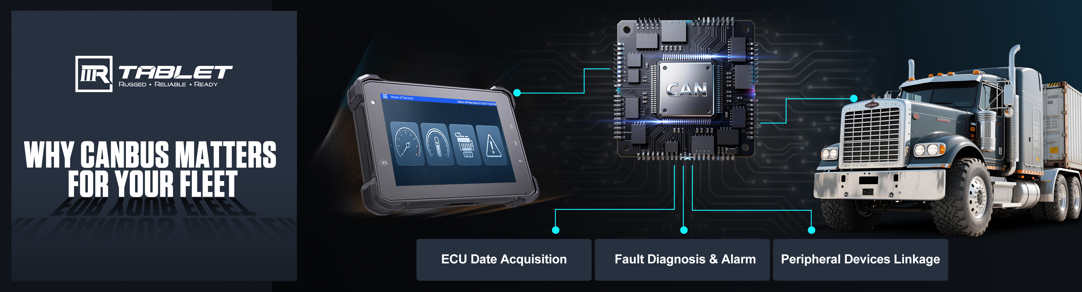
 In construction machinery, modern agricultural equipment, passenger coaches and other sectors, the CAN bus serves as the core communication backbone of the complete vehicle electronic control system, responsible for data transmission and command interaction between the engine, gearbox and external sensors. As the core human-machine interaction and data collection terminal in the cab, the number and performance of CAN channels on rugged vehicle-mounted tablets directly determine the integrity of vehicle data collection and communication stability. This article will explain the key differences between single CAN and dual CAN, as well as their main application areas, to help customer avoid common procurement pitfalls such as software-simulated CAN and gateway-expanded channels falsely marketed as native multi-CAN hardware.
Native Independent CAN Hardware Channels vs. Gateway-Expanded / Software-Simulated CAN
The sole criterion for judging the CAN capability of a rugged tablet is whether the mainboard SoC integrates dedicated native CAN controller peripherals. Channels expanded via software-simulated CAN or external USB/Ethernet CAN gateways cannot match native hardware performance, and the fundamental hardware gaps between the two solutions cannot be compensated by software adjustments.
Standard Hardware Configuration of Native CAN
Each channel is equipped with exclusive hardware resources: an independent CAN controller, independent high-speed CAN transceiver, independent terminal matching resistor, isolated power supply plus digital isolation circuit, and independent surge protection TVS. The power supply, ground and signal circuits of all channels are fully electrically isolated. Short circuits, electrostatic discharge or surge interference on one channel will not propagate to another channel, eliminating the risk of fault cross-spread across network segments.
Core Drawbacks of Gateway-Expanded / Software-Simulated CAN
Gateways are protocol forwarding devices. All CAN messages share the same CPU processing resources and single power domain without hardware isolation. Superimposed data volume from multiple bus segments drastically increases CPU load and introduces millisecond-level forwarding latency. A gateway failure can disrupt all connected bus segments simultaneously, and in severe cases cause full vehicle ECU communication breakdown. Such solutions fail to meet the safety requirements of construction vehicles, and are only suitable for temporary debugging rather than 24/7 fleet continuous monitoring.
Single CAN (Entry-Level Lightweight Model)
Equipped with only one set of CAN controller and single-channel transceiver, supporting connection to just one bus segment. For vehicles with multiple bus architectures, wiring harnesses must be manually unplugged and reconnected to switch data acquisition, making synchronous reading of operating conditions from two independent systems impossible. When a large number of nodes and heavy message loads are on the bus, the bus load rate easily exceeds the 70% risk threshold, resulting in queued message congestion, periodic packet loss and sharp spikes in communication latency. Real-time vehicle condition monitoring and UDS deep diagnostic operations cannot run concurrently; ECU flashing and troubleshooting require disconnecting the vehicle monitoring link and interrupting fleet data uploads. Single CAN is only applicable to basic scenarios featuring single vehicle bus architecture, simple electronic control systems and no depth fault diagnosis requirements.
Dual CAN (Mainstream Standard Model)
The mainboard integrates two fully independent, electrically isolated CAN hardware units. The two channels do not compete for hardware resources, can be independently configured with different baud rates, and support parallel full-speed communication up to 1 Mbps. Synchronous dual-bus data collection, monitoring and diagnostics are supported, covering over 90% of regular operating conditions for heavy-duty vehicles, making it the mainstream configuration for construction, freight and agricultural machinery industries.
1.Synchronous Dual-Bus Data Collection for Full Coverage of Operating Data:
Channel 1 connects to the J1939 power bus (engine, transmission, braking system), while Channel 2 connects to the hydraulic bus or body control bus. Operators can view operating status on tablet, and the backend platform aggregates operational data in real time without wiring harness switching or time-sharing data collection.
2.Parallel Monitoring and Diagnostics for Better Maintenance:
Channel 1 maintains 24/7 real-time upload of vehicle status, fuel consumption and fault alarms for continuous fleet supervision. Channel 2 executes UDS deep fault diagnostics and ECU program flashing without interrupting monitoring, drastically improving fleet maintenance efficiency.
3.Isolation Between Original Vehicle Bus and Peripherals to Eliminate Interference:
Dedicated channels separate the vehicle’s core electronic control system from external peripherals. Malfunctions or surge interference from peripherals remain confined to a single channel and cannot intrude on the original power bus, guaranteeing stable and safe operation of the vehicle’s full electronic control system.
Targeted Selection Guide: Optimal CAN Configurations for Different Operating Scenarios
1.Select Single CAN for:
Light-duty logistics delivery vehicles, small in-factory forklifts and transfer carts; use cases requiring only basic positioning, vehicle speed and fuel consumption reading, with no fault diagnosis or hydraulic/agricultural implement peripherals.
2.Select Dual CAN for:
Small and medium-sized excavators, loaders and road rollers; standard heavy trucks, muck trucks and passenger coaches; small and medium tractors and harvesters; regular fleet monitoring and vehicle maintenance diagnostic projects.
Conclusion
CAN bus channel configuration is a core indicator determining the operating condition adaptability of rugged vehicle-mounted tablets, rather than an optional auxiliary parameter. Reasonable selection of CAN channel configurations based on operating conditions effectively avoids issues including insufficient system compatibility and repeated retrofits, making it a critical link in hardware selection for intelligent vehicle projects.
3Rtablet’s full lineup of rugged vehicle-mounted tablets covers single CAN and dual CAN specifications with screen sizes of 5, 7 and 10 inches. Standard features include wide voltage input of 8–36 V, IP67 dust and water resistance, wide operating temperature range of -10 °C to 65 °C, and MIL-STD-810G shock and vibration resistance. OEM and ODM customization services are available. We can design exclusive hardware solutions tailored to your vehicle bus architecture, operating conditions and project requirements. Feel free to contact us for more information.
Post time: Jul-29-2026
